Measuring Feeders
Before any actual measuring takes place, the feeders must first be written up onto a feeder take-off sheet. This information will be obtained either from the distribution riser diagram or the panelboard schedule sheets.
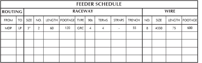
Example:
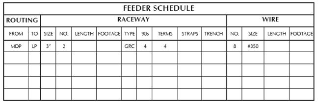
The example shows that the feeder from MDP to panel LP is a parallel run of 2-3” conduits. The type of conduit is a galvanized rigid steel with four elbows and four bushings. The total number of conductors in the run is eight (2x4 per run) and the size of the conductors is #350 MCM.
As each feeder is listed on the FEEDER SCHEDULE, color the feeder on the riser diagram with an orange pencil.
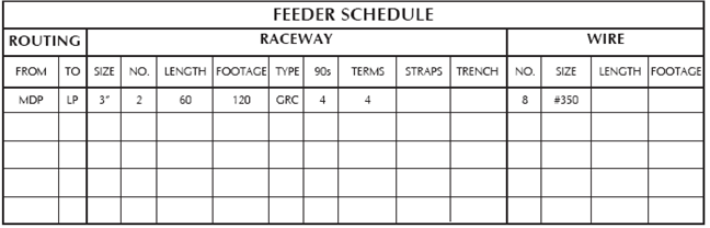
With the completed FEEDER SCHEDULE sheet and a measuring scale, turn to the floor plans and begin measuring the feeders. As each feeder is measured, additional footage of pipe must be added for “turning up” or for “dropping down”. When the distance is determined, write that distance in the Length column; this will be the length of the feeder run. The actual footage of conduit in that particular run will be determined by multiplying the number of conduits in the run by the length of the run.
Example:
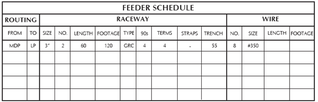
If the feeder is overhead, write the number of straps or clamps that will be required to support the conduit. If the feeder run is underground, write in the length of trench. Be sure to fill in these columns; if the straps are not used, indicate this by putting a dash mark (-) in the Strap column.
Example:
Add the necessary make-up and waste to the length of the feeder run to find the wire length. Obtain the total wire footage by multiplying the number of conductors in the run by the length of the feeder run.
Example: